

Cluster#
In this section we introduce how to configure Qblox Clusters and the options available for them via Quantify. For information about their lower-level functionality, you can consult the Qblox Instruments documentation. For information on the process of compilation to hardware, see Tutorial: Compiling to Hardware.
General hardware compilation config structure, example#
We start by looking at an example config for a single cluster. The hardware compilation configuration specifies which modules are used (Hardware Description) and how they are connected to the quantum device (Connectivity), along with some (optional) Hardware Options, like modulation frequencies, gains and attenuations, or mixer corrections. The general structure of this configuration file is described in the Hardware compilation configuration section of the User guide.
 1hardware_compilation_cfg = {
 2    "config_type": "quantify_scheduler.backends.qblox_backend.QbloxHardwareCompilationConfig",
 3    "hardware_description": {
 4        "cluster0": {
 5            "instrument_type": "Cluster",
 6            "ref": "internal",
 7            "modules": {
 8                "1": {
 9                    "instrument_type": "QCM"
10                },
11                "2": {
12                    "instrument_type": "QCM_RF"
13                },
14            }
15        },
16        "lo0": {
17            "instrument_type": "LocalOscillator",
18            "power": 20
19        },
20        "iq_mixer_lo0": {
21            "instrument_type": "IQMixer"
22        }
23    },
24    "hardware_options": {
25        "modulation_frequencies": {
26            "q4:mw-q4.01": {
27                "interm_freq": 200e6
28            },
29            "q5:mw-q5.01": {
30                "interm_freq": 50e6
31            },
32        },
33        "mixer_corrections": {
34            "q4:mw-q4.01": {
35                "amp_ratio": 0.9999,
36                "phase_error": -4.2
37            }
38        },
39    },
40    "connectivity": {
41        "graph": [
42            ("cluster0.module1.complex_output_0", "iq_mixer_lo0.if"),
43            ("lo0.output", "iq_mixer_lo0.lo"),
44            ("iq_mixer_lo0.rf", "q4:mw"),
45            ("cluster0.module2.complex_output_0", "q5:mw"),
46        ]
47    },
48}
Notice the QbloxHardwareCompilationConfig config type is used.
In the example, the cluster is specified using an instrument with "instrument_type": "Cluster". In the backend, the cluster instrument functions as a collection of modules.
The only instrument types that can be at the top level are:
"Cluster","LocalOscillator"."IQMixer"."OpticalModulator".
Hardware description for clusters#
To compile to a cluster, one should include a valid ClusterDescription in the "hardware_description" part of the hardware compilation config.
The name of the cluster (the key of the structure, "cluster0" in the example) can be chosen freely.
- class ClusterDescription(/, **data: Any)[source]
Information needed to specify a Cluster in the
CompilationConfig.- instrument_type: Literal['Cluster'][source]
The instrument type, used to select this datastructure when parsing a
CompilationConfig.
- modules: dict[int, ClusterModuleDescription][source]
Description of the modules of this Cluster, using slot index as key.
- ref: Literal['internal'] | Literal['external'][source]
The reference source for the instrument.
Here the modules are described by their respective ClusterModuleDescription. For example, a QRM-RF module is described by
- class QRMRFDescription(/, **data: Any)[source]
Information needed to specify a QRM-RF in the
QbloxHardwareCompilationConfig.- complex_input_0: ComplexChannelDescription | None = None[source]
Description of the complex input channel on this QRM, corresponding to port I1.
- complex_output_0: ComplexChannelDescription | None = None[source]
Description of the complex output channel on this QRM, corresponding to port O1.
- digital_output_0: DigitalChannelDescription | None = None[source]
Description of the digital (marker) output channel on this QRM, corresponding to port M1.
- digital_output_1: DigitalChannelDescription | None = None[source]
Description of the digital (marker) output channel on this QRM, corresponding to port M2.
- instrument_type: Literal['QRM_RF'] = 'QRM_RF'[source]
The instrument type of this module.
Channel-specific settings can be set in the {Complex,Real,Digital}ChannelDescription datastructures.
For example, for a QRM-RF module, the ComplexChannelDescription is used to describe the settings for the complex output.
To use the default settings, one can omit the channel description from the ClusterModuleDescription, as is done in the General hardware compilation config structure, example above.
For a complex input/output, this datastructure is:
- class ComplexChannelDescription(/, **data: Any)[source]
Information needed to specify an complex input/output in the
QbloxHardwareCompilationConfig.- distortion_correction_latency_compensation: int[source]
Delay compensation setting that either delays the signal by the amount chosen by the settings or not.
- downconverter_freq: float | None = None[source]
Downconverter frequency that should be taken into account w hen determining the modulation frequencies for this channel. Only relevant for users with custom Qblox downconverter hardware.
Marker configuration#
The markers can be configured by adding a "marker_debug_mode_enable" key to the ComplexChannelDescription
(or RealChannelDescription).
If the value is set to True, each pulse and acquisition defined for this channel will be accompanied by a 4 ns trigger pulse on the marker located next to the I/O port.
The marker will be pulled high at the same time as the module starts playing or acquiring.
 1hardware_compilation_cfg = {
 2    "config_type": "quantify_scheduler.backends.qblox_backend.QbloxHardwareCompilationConfig",
 3    "hardware_description": {
 4        "cluster0": {
 5            "instrument_type": "Cluster",
 6            "ref": "internal",
 7            "modules": {
 8                "1": {
 9                    "instrument_type": "QCM",
10                    "complex_output_0": {
11                        "marker_debug_mode_enable": True,
12                    }
13                }
14            }
15        }
16    },
17    "hardware_options": {...},
18    "connectivity": {...},
19}
Write sequencer program to files#
It is possible to optionally include the "sequence_to_file" key. If set to True, a file will be created for each sequencer with the program that’s uploaded to the sequencer with the filename <data_dir>/schedules/<year><month><day>-<hour><minute><seconds>-<milliseconds>-<random>_<port>_<clock>.json in a JSON format, where <random> is 6 random characters in the range 0-9, a-f. The value defaults to False in case "sequence_to_file" is not included.
It is also possible to set this parameter per module via its module configuration.
 1hardware_compilation_cfg = {
 2    "config_type": "quantify_scheduler.backends.qblox_backend.QbloxHardwareCompilationConfig",
 3    "hardware_description": {
 4        "cluster0": {
 5            "instrument_type": "Cluster",
 6            "ref": "internal",
 7            "sequence_to_file": True,
 8            "modules": {...}
 9        }
10    },
11    "hardware_options": {...},
12    "connectivity": {...}
13}
Downconverter#
Note
This section is only relevant for users with custom Qblox downconverter hardware.
Some users employ a custom Qblox downconverter module. In order to use it with this backend, we specify a "downconverter_freq" entry in the outputs that are connected to this module, as exemplified below.
The result is that the clock frequency is downconverted such that the signal reaching the target port is at the desired clock frequency, i.e. \(f_\mathrm{out} = f_\mathrm{downconverter} - f_\mathrm{in}\).
For baseband modules, downconversion will not happen if "mix_lo" is not True and there is no external LO specified ("mix_lo" is True by default). For RF modules, the "mix_lo" setting is not used (effectively, always True). Also see helper function determine_clock_lo_interm_freqs().
 1hardware_compilation_cfg = {
 2    "config_type": "quantify_scheduler.backends.qblox_backend.QbloxHardwareCompilationConfig",
 3    "hardware_description": {
 4        "cluster0": {
 5            "instrument_type": "Cluster",
 6            "ref": "internal",
 7            "modules": {
 8                "1": {
 9                    "instrument_type": "QCM",
10                    "complex_output_0": {
11                        "downconverter_freq": 9e9,
12                        "mix_lo": True,
13                    }
14                },
15                "2": {
16                    "instrument_type": "QCM_RF",
17                    "complex_output_0": {
18                        "downconverter_freq": 9e9,
19                    }
20                },
21            }
22        },
23        "lo0": {"instrument_type": "LocalOscillator", "power": 20},
24        "iq_mixer_lo0": {"instrument_type": "IQMixer"},
25    },
26    "hardware_options": {
27        "modulation_frequencies": {
28            "q0:mw-q0.01": {
29                "interm_freq": 50e6
30            },
31            "q1:mw-q1.01": {
32                "interm_freq": 50e6
33            },
34        },
35    },
36    "connectivity": {
37        "graph": [
38            ("cluster0.module1.complex_output_0", "iq_mixer_lo0.if"),
39            ("lo0.output", "iq_mixer_lo0.lo"),
40            ("iq_mixer_lo0.rf", "q0:mw"),
41            ("cluster0.module2.complex_output_0", "q1:mw"),
42        ]
43    },
44}
Connectivity#
The Connectivity describes how the inputs/outputs of the cluster modules are connected to ports on the QuantumDevice. As described in Connectivity in the User guide, the connectivity datastructure can be parsed from a list of edges, which are described by a pair of strings that each specify a port on the quantum device, on the cluster modules, or on other auxiliary instruments (like external IQ mixers).
Each input/output node of the cluster should be specified in the connectivity as "{cluster_name}.module{module_slot_index}.{channel_name}". For each module, the possible input/output names are the same as the allowed fields in the corresponding ClusterModuleDescription datastructure:
for
"QCM":"complex_output_{0,1}","real_output_{0,1,2,3}","digital_output_{0,1,2,3}",for
"QRM":"complex_{output,input}_0","real_{output,input}_{0,1}","digital_output_{0,1,2,3}",for
"QCM_RF":"complex_output_{0,1}","digital_output_{0,1}",for
"QRM_RF":"complex_{output,input}_0","digital_output_{0,1}",for
"QTM":"digital_{output,input}_{0,1,2,3,4,5,6,7}".
Note
For RF hardware, if an output is unused, it will be turned off. This is to ensure that unused local oscillators do not interfere with used outputs.
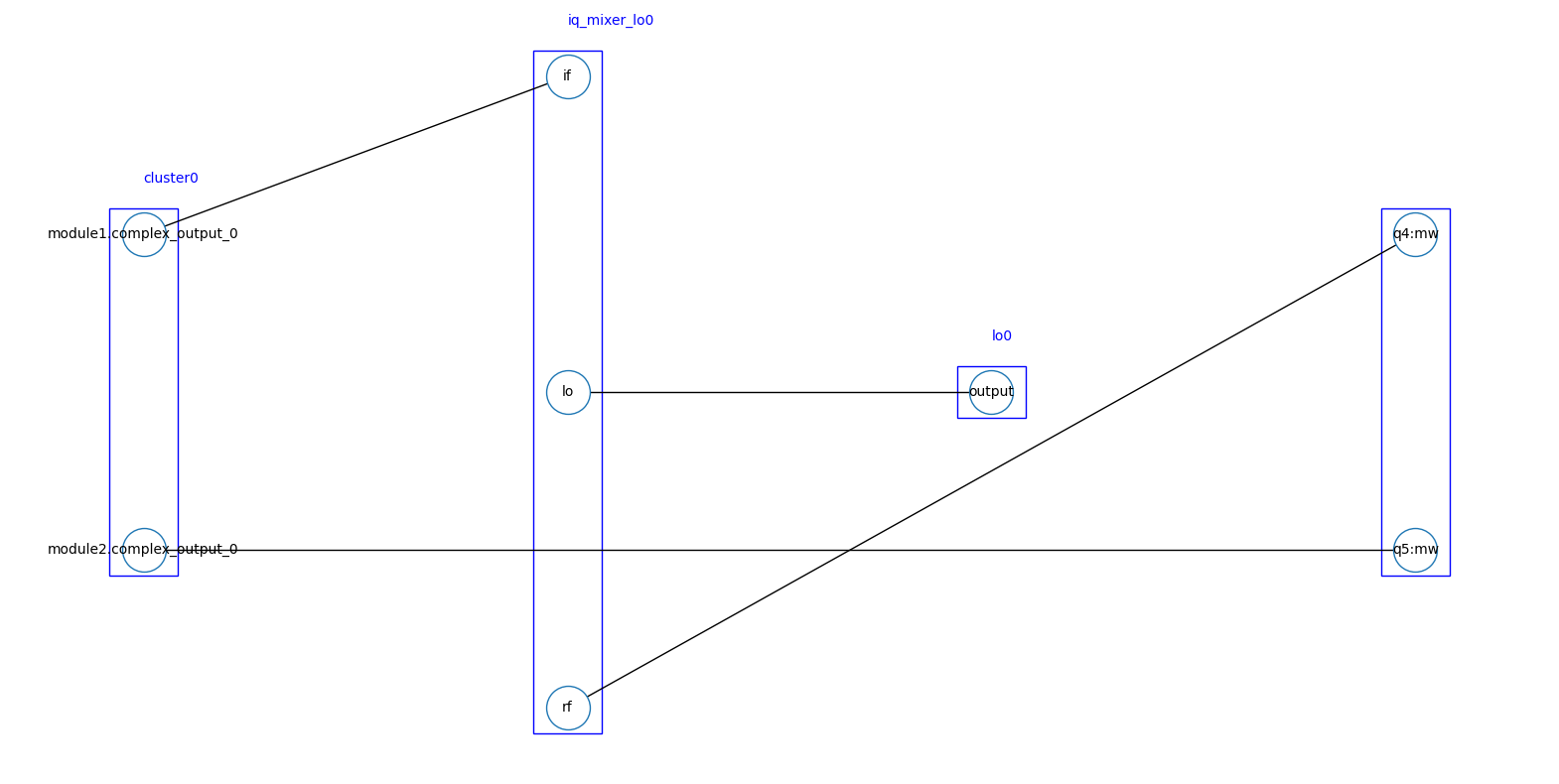
The connectivity can be visualized using:
from quantify_scheduler.backends.types.common import Connectivity

connectivity = Connectivity.model_validate(hardware_compilation_cfg["connectivity"])
connectivity.draw()
<Axes: >
Ports and clocks#
Each module can target at most 6 port-clock combinations within a schedule. Each of these port-clock combinations is associated with one sequencer in the Qblox hardware. See the Ports and clocks section in the User guide for more information on the role of ports and clocks within quantify-scheduler.
Changed in version 0.21.0: The alphabetical order of the module portclocks determines the order of sequencer instantiation (e.g. the sequencer associated with q0:mw-q0.01 is instantiated before the sequencer of q0:res-q0.ro).
 1hardware_compilation_cfg = {
 2    "config_type": "quantify_scheduler.backends.qblox_backend.QbloxHardwareCompilationConfig",
 3    "hardware_description": {
 4        "cluster0": {
 5            "instrument_type": "Cluster",
 6            "ref": "internal",
 7            "modules": {
 8                "1": {
 9                    "instrument_type": "QCM"
10                },
11            }
12        },
13    },
14    "hardware_options": {},
15    "connectivity": {
16        "graph": [
17            ("cluster0.module1.complex_output_0", "q0:mw"),
18        ]
19    }
20}
21
22sched = Schedule("Single pulse schedule")
23sched.add(
24    SquarePulse(amp=1, duration=1e-6, port="q0:mw", clock="q0.01")
25)
26sched.add_resource(ClockResource(name="q0.01", freq=200e6))
Note
With gate-level operations, you have to follow strict port naming:
"<device element name>:mw"forRxyoperation (and its derived operations),"<device element name>:res"for any measure operation,"<device element name>:fl"for the flux port.
Complex channel#
A complex channel is defined by including "complex_output_<n>" or "complex_input_<n>" in the connectivity. Complex outputs (e.g. complex_output_0) are used for playbacks, while complex inputs (e.g. complex_input_0) are used for acquisitions.
Note
Operations involving both an output and an input channel (e.g.Measure) require writing both the output and input channel names in the connectivity, both using the same port. Output and input channels of different modes (e.g. complex_output_0 + real_input_0) using the same port are not allowed.
 1hardware_compilation_cfg = {
 2    "version": "0.2",
 3    "config_type": "quantify_scheduler.backends.qblox_backend.QbloxHardwareCompilationConfig",
 4    "hardware_description": {
 5        "cluster0": {
 6            "instrument_type": "Cluster",
 7            "ref": "internal",
 8            "modules": {
 9                "1": {
10                    "instrument_type": "QRM"
11                },
12            }
13        }
14    }
15    "hardware_options": {...},
16    "connectivity": {
17        "graph": [
18            ("cluster0.module1.complex_output_0", "q0:res"),
19            ("cluster0.module1.complex_input_0", "q0:res")
20        ]
21    }
22}
Real channel#
A real channel is defined by including "real_output_<n>" or "real_input_<n>" in the connectivity. Real outputs (e.g. real_output_0) are used for playbacks, while real inputs (e.g. real_input_0) are used for acquisitions.
Note that the backend throws an error when using a real channel for pulses with an imaginary component. For example, square and ramp pulses are allowed, but DRAG pulses are not.
Note
Operations involving both an output and an input channel (e.g.Measure) require writing both the output and input channel names in the connectivity, both using the same port. Output and input channels of different modes (e.g. complex_output_0 + real_input_0) using the same port are not allowed.
 1hardware_compilation_cfg = {
 2    "version": "0.2",
 3    "config_type": "quantify_scheduler.backends.qblox_backend.QbloxHardwareCompilationConfig",
 4    "hardware_description": {
 5        "cluster0": {
 6            "instrument_type": "Cluster",
 7            "ref": "internal",
 8            "modules": {
 9                "1": {
10                    "instrument_type": "QRM"
11                },
12            }
13        }
14    }
15    "hardware_options": {...},
16    "connectivity": {
17        "graph": [
18            ("cluster0.module1.real_output_0", "q0:res"),
19            ("cluster0.module1.real_input_0", "q0:res")
20        ]
21    }
22}
Digital channel#
The inputs and outputs of the QTM and the markers of QCM/QRM (RF) can be controlled by defining a digital channel. Only certain operations are possible on digital channels, such as the MarkerPulse. A digital channel is defined by adding a "digital_output_n" or "digital_input_n" to the connectivity, where n corresponds to port n+1 on the device.
 1hardware_compilation_cfg = {
 2    "config_type": "quantify_scheduler.backends.qblox_backend.QbloxHardwareCompilationConfig",
 3    "hardware_description": {...},
 4    "hardware_options": {...},
 5    "connectivity": {
 6        "graph": [
 7            ("cluster0.module1.digital_output_0", "q0:switch")
 8        ]
 9    }
10}
The MarkerPulse is defined by adding a MarkerPulse to the sequence in question. It takes the same parameters as any other pulse.
schedule.add(MarkerPulse(duration=52e-9, port="q0:switch"))
Clock names#
Clocks in digital channels serve simply as a label and are automatically set to "digital" at initialization of digital-channel-only operations, such as the :class:~quantify_scheduler.operations.pulse_library.MarkerPulse. However, it is also possible to specify a custom clock name (for example, a clock name from the device configuration, like qe0.ge0). This makes it possible to connect a digital channel to a given port-clock combination in a device element, for example. Similar to clocks for non-digital channels, the clock must be either
specified in the device configuration,
added to the
Scheduleas aClockResource, ora clock that is present by default in the schedule resources, i.e.
"digital"or"cl0.baseband".
External IQ mixers, optical modulators and local oscillators#
Baseband modules can be connected to external IQ mixers, optical modulators and local oscillators. For local oscillators coupled with IQ mixers, you should add a IQMixerDescription and LocalOscillatorDescription to the "hardware_description" part of the hardware compilation config, and specify the connections of the "if", "lo" and "rf" ports on the IQ mixer in the "connectivity" part of the hardware compilation config. The compiler will then use this information to assign the pulses and acquisitions to the port on the baseband module that is connected to the "if" port on the IQ mixer, and set the local oscillator and intermodulation frequencies accordingly.
For local oscillators coupled with optical modulators, you should instead add a OpticalModulatorDescription and use the "if", "lo" and "out" ports. For a qubit "qi", local oscillators names must include "green_laser", "spinpump_laser" or "red_laser" (these are associated with clocks "qi.ionization", "qi.ge1" and "qi.ge0", respectively).
Local Oscillator Description
It is possible to add "generic_icc_name" as an optional parameter to the local oscillator hardware description, but only the default name "generic" is supported currently with the Qblox backend.
 1hardware_compilation_cfg = {
 2    "config_type": "quantify_scheduler.backends.qblox_backend.QbloxHardwareCompilationConfig",
 3    "hardware_description": {
 4        "cluster0": {...},
 5        "lo0": {
 6            "instrument_type": "LocalOscillator",
 7            "power": 20
 8        },
 9        "iq_mixer_lo0": {"instrument_type": "IQMixer"},
10    },
11    "hardware_options": {
12        "modulation_frequencies": {
13            "q1:mw-q1.01": {
14                "lo_freq": 5e9
15            }
16        }
17    },
18    "connectivity": {
19        "graph": [
20            ("cluster0.module1.complex_output_1", "iq_mixer_lo0.if"),
21            ("lo0.output", "iq_mixer_lo0.lo"),
22            ("iq_mixer_lo0.rf", "q1:mw"),
23        ]
24    }
25}
Frequency multiplexing#
It is possible to do frequency multiplexing of the signals without changing the connectivity: by adding operations on the same port, but with different clocks.
 1hardware_compilation_cfg = {
 2    "config_type": "quantify_scheduler.backends.qblox_backend.QbloxHardwareCompilationConfig",
 3    "hardware_description": {
 4        "cluster0": {
 5            "instrument_type": "Cluster",
 6            "ref": "internal",
 7            "modules": {
 8                "1": {
 9                    "instrument_type": "QCM"
10                },
11            }
12        },
13    },
14    "hardware_options": {},
15    "connectivity": {
16        "graph": [
17            ("cluster0.module1.complex_output_0", "q0:mw"),
18        ]
19    }
20}
21
22sched = Schedule("Multiplexed schedule")
23sched.add(
24    SquarePulse(amp=1, duration=1e-6, port="q0:mw", clock="q0.01")
25)
26sched.add(
27    SquarePulse(amp=0.5, duration=1e-6, port="q0:mw", clock="q0.some_other_clock")
28)
29sched.add_resource(ClockResource(name="q0.01", freq=200e6))
30sched.add_resource(ClockResource(name="q0.some_other_clock", freq=100e6))
In the given example, we add two pulses on the same port but with different clocks. Now any signal on port "q0:mw" with clock "some_other_clock" will be added digitally to the signal with the same port but clock "q0.01".
The Qblox modules have six sequencers available, which sets the upper limit to our multiplexing capabilities.
Hardware options#
The QbloxHardwareOptions datastructure contains the settings used in compiling from the quantum-device layer to a set of instructions for the control hardware.
- class QbloxHardwareOptions(/, **data: Any)[source]
Datastructure containing the hardware options for each port-clock combination.
Example
Here, the HardwareOptions datastructure is created by parsing a dictionary containing the relevant information.
import pprint
from quantify_scheduler.schemas.examples.utils import (
    load_json_example_scheme
)
from quantify_scheduler.backends.types.qblox import (
    QbloxHardwareOptions
)
qblox_hw_options_dict = load_json_example_scheme(
    "qblox_hardware_config_transmon.json")["hardware_options"]
pprint.pprint(qblox_hw_options_dict)
{'distortion_corrections': {'q0:fl-cl0.baseband': {'clipping_values': [-2.5,
                                                                       2.5],
                                                   'filter_func': 'scipy.signal.lfilter',
                                                   'input_var_name': 'x',
                                                   'kwargs': {'a': [1],
                                                              'b': [0,
                                                                    0.25,
                                                                    0.5]}}},
 'input_att': {'q0:res-q0.ro': 4, 'q5:res-q5.ro': 10},
 'input_gain': {'q4:res-q4.ro': {'gain_I': 2, 'gain_Q': 3}},
 'latency_corrections': {'q4:mw-q4.01': 8e-09, 'q5:mw-q5.01': 4e-09},
 'mixer_corrections': {'q4:mw-q4.01': {'amp_ratio': 0.9999,
                                       'phase_error': -4.2},
                       'q4:res-q4.ro': {'amp_ratio': 0.9997,
                                        'dc_offset_i': -0.054,
                                        'dc_offset_q': -0.034,
                                        'phase_error': -4.0}},
 'modulation_frequencies': {'q0:mw-q0.01': {'interm_freq': 50000000.0,
                                            'lo_freq': None},
                            'q0:res-q0.ro': {'interm_freq': None,
                                             'lo_freq': 7800000000.0},
                            'q4:mw-q4.01': {'interm_freq': 200000000.0,
                                            'lo_freq': None},
                            'q4:res-q4.ro': {'interm_freq': None,
                                             'lo_freq': 7200000000.0},
                            'q5:mw-q5.01': {'interm_freq': 50000000.0,
                                            'lo_freq': None},
                            'q5:res-q5.ro': {'interm_freq': 50000000.0},
                            'q6:mw-q6.01': {'lo_freq': 5000000000.0},
                            'q7:mw-q7.01': {'lo_freq': 5000000000.0},
                            'q8:mw-q8.01': {'interm_freq': 50000000.0,
                                            'lo_freq': None},
                            'q8:res-q8.ro': {'interm_freq': 50000000.0,
                                             'lo_freq': None}},
 'output_att': {'q0:mw-q0.01': 4,
                'q0:res-q0.ro': 12,
                'q5:mw-q5.01': 4,
                'q6:mw-q6.01': 6},
 'sequencer_options': {'qe0:optical_readout-qe0.ge0': {'ttl_acq_threshold': 0.5}}}
The dictionary can be parsed using the
model_validatemethod.qblox_hw_options = QbloxHardwareOptions.model_validate(qblox_hw_options_dict) qblox_hw_options
QbloxHardwareOptions(crosstalk=None, latency_corrections={'q4:mw-q4.01': 8e-09, 'q5:mw-q5.01': 4e-09}, distortion_corrections={'q0:fl-cl0.baseband': SoftwareDistortionCorrection(filter_func='scipy.signal.lfilter', input_var_name='x', kwargs={'b': [0, 0.25, 0.5], 'a': [1]}, clipping_values=[-2.5, 2.5], sampling_rate=1000000000.0)}, modulation_frequencies={'q0:res-q0.ro': ModulationFrequencies(interm_freq=None, lo_freq=7800000000.0), 'q0:mw-q0.01': ModulationFrequencies(interm_freq=50000000.0, lo_freq=None), 'q4:mw-q4.01': ModulationFrequencies(interm_freq=200000000.0, lo_freq=None), 'q4:res-q4.ro': ModulationFrequencies(interm_freq=None, lo_freq=7200000000.0), 'q5:mw-q5.01': ModulationFrequencies(interm_freq=50000000.0, lo_freq=None), 'q5:res-q5.ro': ModulationFrequencies(interm_freq=50000000.0, lo_freq=None), 'q6:mw-q6.01': ModulationFrequencies(interm_freq=None, lo_freq=5000000000.0), 'q7:mw-q7.01': ModulationFrequencies(interm_freq=None, lo_freq=5000000000.0), 'q8:mw-q8.01': ModulationFrequencies(interm_freq=50000000.0, lo_freq=None), 'q8:res-q8.ro': ModulationFrequencies(interm_freq=50000000.0, lo_freq=None)}, mixer_corrections={'q4:mw-q4.01': QbloxMixerCorrections(dc_offset_i=None, dc_offset_q=None, amp_ratio=0.9999, phase_error=-4.2, auto_lo_cal=<LoCalEnum.OFF: 'off'>, auto_sideband_cal=<SidebandCalEnum.OFF: 'off'>), 'q4:res-q4.ro': QbloxMixerCorrections(dc_offset_i=-0.054, dc_offset_q=-0.034, amp_ratio=0.9997, phase_error=-4.0, auto_lo_cal=<LoCalEnum.OFF: 'off'>, auto_sideband_cal=<SidebandCalEnum.OFF: 'off'>)}, input_gain={'q4:res-q4.ro': ComplexInputGain(gain_I=2, gain_Q=3)}, output_att={'q0:mw-q0.01': 4, 'q0:res-q0.ro': 12, 'q5:mw-q5.01': 4, 'q6:mw-q6.01': 6}, input_att={'q0:res-q0.ro': 4, 'q5:res-q5.ro': 10}, sequencer_options={'qe0:optical_readout-qe0.ge0': SequencerOptions(init_offset_awg_path_I=0.0, init_offset_awg_path_Q=0.0, init_gain_awg_path_I=1.0, init_gain_awg_path_Q=1.0, ttl_acq_threshold=0.5, qasm_hook_func=None)}, digitization_thresholds=None)- digitization_thresholds: dict[str, DigitizationThresholds] | None = None[source]
Dictionary containing the digitization threshold settings for QTM modules. These are the settings that determine the voltage thresholds above which input signals are registered as high.
- distortion_corrections: dict[str, quantify_scheduler.backends.types.common.SoftwareDistortionCorrection | QbloxHardwareDistortionCorrection | list[QbloxHardwareDistortionCorrection]] | None = None[source]
Dictionary containing the distortion corrections (values) that should be applied to waveforms on a certain port-clock combination (keys).
- input_att: dict[str, InputAttenuation] | None = None[source]
Dictionary containing the attenuation settings (values) that should be applied to the inputs that are connected to a certain port-clock combination (keys).
- input_gain: dict[str, RealInputGain | ComplexInputGain] | None = None[source]
Dictionary containing the input gain settings (values) that should be applied to the inputs that are connected to a certain port-clock combination (keys).
- latency_corrections: dict[str, LatencyCorrection] | None = None[source]
Dictionary containing the latency corrections (values) that should be applied to operations on a certain port-clock combination (keys).
- mixer_corrections: dict[str, QbloxMixerCorrections] | None = None[source]
Dictionary containing the qblox-specific mixer corrections (values) that should be used for signals on a certain port-clock combination (keys).
- modulation_frequencies: dict[str, ModulationFrequencies] | None = None[source]
Dictionary containing the modulation frequencies (values) that should be used for signals on a certain port-clock combination (keys).
- output_att: dict[str, OutputAttenuation] | None = None[source]
Dictionary containing the attenuation settings (values) that should be applied to the outputs that are connected to a certain port-clock combination (keys).
- sequencer_options: dict[str, SequencerOptions] | None = None[source]
Dictionary containing the options (values) that should be set on the sequencer that is used for a certain port-clock combination (keys).
Modulation frequencies#
The aim of quantify-scheduler is to only specify the final RF frequency when the signal arrives at the chip, rather than any parameters related to I/Q modulation. However, you still need to provide some parameters for the up/downconversion.
The backend assumes that upconversion happens according to the relation
These frequencies are specified for each port-clock combination in the "modulation_frequencies" in the "hardware_options".
You can specify \(f_{RF}\) in multiple ways. You can specify it when you add a ClockResource with freq argument to your Schedule, or when you specify the BasicTransmonElement.clock_freqs.
Note
If you use gate-level operations, you have to follow strict rules for the naming of the clock resource, for each kind of operation:
"<device element name>.01"forRxyoperation (and its derived operations),"<device element name>.ro"for any measure operation,"<device element name>.12"for the \(|1\rangle \rightarrow |2\rangle\) transition.
Then, different options are possible depending on the type of module:
For baseband modules, you can optionally specify a local oscillator by its name using the
"lo_name"key in the Connectivity. If you specify it, the"lo_freq"key in the"modulation_frequencies"(see the example below) specifies \(f_{LO}\) of this local oscillator. Otherwise, \(f_{LO} = 0\) and \(f_{RF} = f_{IF}\). \(f_{RF} = f_{IF}\) can also be set in the hardware options explicitly with the"interm_freq"key in the"modulation_frequencies".For RF modules, you can specify \(f_{IF}\) through the
"interm_freq"key, and/or you can specify the local oscillator frequency for the output used for the port-clock combination with the"lo_freq", because they have internal local oscillators. Note, if you specify both, the relationship between these frequencies should hold, otherwise you get an error message. It’s important to note, that fast frequency sweeps only work when \(f_{LO}\) is fixed, and \(f_{IF}\) is unspecified. Because of this, it is generally advised to specify \(f_{LO}\) only.
 1from quantify_scheduler import Schedule
 2from quantify_scheduler.backends.graph_compilation import SerialCompiler
 3from quantify_scheduler.device_under_test.quantum_device import QuantumDevice
 4from quantify_scheduler.operations.pulse_library import SquarePulse
 5from quantify_scheduler.resources import ClockResource
 6
 7hardware_compilation_cfg = {
 8    "config_type": "quantify_scheduler.backends.qblox_backend.QbloxHardwareCompilationConfig",
 9    "hardware_description": {
10        "cluster0": {
11            "instrument_type": "Cluster",
12            "ref": "internal",
13            "modules": {
14                "1": {
15                    "instrument_type": "QCM"
16                },
17                "2": {
18                    "instrument_type": "QCM_RF"
19                },
20            }
21        },
22        "lo0": {"instrument_type": "LocalOscillator", "power": 20},
23        "iq_mixer_lo0": {"instrument_type": "IQMixer"},
24    },
25    "hardware_options": {
26        "modulation_frequencies": {
27            "q1:mw-q1.01": {
28                "lo_freq": 5e9
29            },
30            "q2:mw-q2.01": {
31                "lo_freq": 7e9
32            },
33            "q3:mw-q3.01": {
34                "interm_freq": 50e6
35            },
36        },
37    },
38    "connectivity": {
39        "graph": [
40            ("cluster0.module1.complex_output_0", "q0:mw"),
41            ("cluster0.module1.complex_output_1", "iq_mixer_lo0.if"),
42            ("lo0.output", "iq_mixer_lo0.lo"),
43            ("iq_mixer_lo0.rf", "q1:mw"),
44            ("cluster0.module2.complex_output_0", "q2:mw"),
45            ("cluster0.module2.complex_output_1", "q3:mw"),
46        ]
47    }
48}
49
50test_sched = Schedule("test_sched")
51test_sched.add_resource(ClockResource(name="q0.01", freq=8e9))
52test_sched.add_resource(ClockResource(name="q1.01", freq=9e9))
53test_sched.add_resource(ClockResource(name="q2.01", freq=8e9))
54test_sched.add_resource(ClockResource(name="q3.01", freq=9e9))
55
56test_sched.add(SquarePulse(amp=1, duration=1e-6, port="q0:mw", clock="q0.01"))
57test_sched.add(SquarePulse(amp=0.25, duration=1e-6, port="q1:mw", clock="q1.01"))
58test_sched.add(SquarePulse(amp=0.25, duration=1e-6, port="q2:mw", clock="q2.01"))
59test_sched.add(SquarePulse(amp=0.25, duration=1e-6, port="q3:mw", clock="q3.01"))
60
61quantum_device = QuantumDevice("DUT")
62quantum_device.hardware_config(hardware_compilation_cfg)
63compiler = SerialCompiler(name="compiler")
64_ = compiler.compile(
65    schedule=test_sched, config=quantum_device.generate_compilation_config()
66)
In the baseband modules of the example above, "complex_output_0"’s \(f_{IF}\) is the same as the "q0.01" clock resource’s frequency, and "complex_output_1"’s \(f_{IF}\) is calculated using the frequency of "lo1" (specified in "modulation_frequencies" under "q1:mw-q1.01" ) and "q1.01". For the RF modules of the same example, "complex_output_0"’s \(f_{IF}\) is calculated using the provided "lo_freq" for "q2:mw-q2.01" and the frequency of "q2.01", and for "complex_output_1", the \(f_{LO}\) is calculated using the provided "interm_freq" for "q3:mw-q3.01" and the frequency of "q3.01".
Mixer corrections#
The backend also supports setting the parameters that are used by the hardware to correct for mixer imperfections in real-time.
We configure this by adding the "mixer_corrections" to the hardware options for a specific port-clock combination. See the following example.
 1hardware_compilation_cfg = {
 2    "config_type": "quantify_scheduler.backends.qblox_backend.QbloxHardwareCompilationConfig",
 3    "hardware_description": {...},
 4    "connectivity": {...},
 5    "hardware_options": {
 6        "mixer_corrections": {
 7            "q4:mw-q4.01": {
 8                "dc_offset_i": -0.054,
 9                "dc_offset_q": -0.034,
10                "amp_ratio": 0.9997,
11                "phase_error": -4.0,
12            }
13        }
14    }
15}
Automatic mixer calibration#
Added in version 0.21.0: Automatic mixer calibration was added.
The mixer correction settings above can also be automatically determined by the hardware. It is possible to calibrate both the LO leakage (controlled by dc_offset_i and dc_offset_q) and the sidebands (controlled by amp_ratio and phase_error), or either one individually.
Automatic LO leakage calibration can be turned on with the setting auto_lo_cal, which can take the values:
"off": no LO leakage calibration,"on_lo_freq_change": only run when changing the LO frequency, and"on_lo_interm_freq_change": run when changing either the LO frequency or the intermediate frequency.
Depending on the exact setting, the module will automatically find values for "dc_offset_i" and "dc_offset_q", which means these fields should not be specified if using automatic calibration.
Automatic sidebands calibration can be turned on with the setting auto_sideband_cal which can take the values "off" and "on_interm_freq_change" (run when changing the intermediate frequency). This will automatically find values for "amp_ratio" and "phase_error", which means these fields should not be specified if using automatic calibration.
The automatic mixer correction settings are also specified in the "mixer_corrections" field in the hardware options. See the following example.
 1hardware_compilation_cfg = {
 2    "config_type": "quantify_scheduler.backends.qblox_backend.QbloxHardwareCompilationConfig",
 3    "hardware_description": {...},
 4    "connectivity": {...},
 5    "hardware_options": {
 6        "mixer_corrections": {
 7            "q4:mw-q4.01": {
 8                "auto_lo_cal": "on_lo_interm_freq_change",
 9                "auto_sideband_cal": "on_interm_freq_change",
10            }
11        }
12    }
13}
Gain and attenuation#
For QRM, QRM-RF and QCM-RF modules you can set the gain and attenuation parameters in dB in the "hardware_options".
Gain configuration#
Note, these parameters only affect the QRM modules. For complex inputs you have to specify a tuple (for the I and Q inputs), and for real inputs a scalar value.
 1hardware_compilation_cfg = {
 2    "config_type": "quantify_scheduler.backends.qblox_backend.QbloxHardwareCompilationConfig",
 3    "hardware_description": {
 4        "cluster0": {
 5            "instrument_type": "Cluster",
 6            "ref": "internal",
 7            "modules": {
 8                "1": {
 9                    "instrument_type": "QRM"
10                },
11                "2": {
12                    "instrument_type": "QRM"
13                },
14            }
15        },
16    },
17    "hardware_options": {
18        "input_gain": {
19            "q0:res-q0.ro": {
20                "gain_I": 2,
21                "gain_Q": 3
22            }
23            "q0:fl-cl0.baseband": 2
24        },
25    },
26    "connectivity": {
27        "graph": [
28            ("cluster0.module1.complex_input_0", "q0:res"),
29            ("cluster0.module2.real_input_0", "q0:fl"),
30        ]
31    }
32}
Attenuation configuration#
The parameters
"output_att"and"input_att"for QRM-RF correspond to the qcodes parameters out0_att and in0_att respectively.The parameter
"output_att"for QCM-RF correspond to the qcodes parameters out0_att and out1_att.
Note, that these parameters only affect RF modules. See Qblox Instruments: QCM-QRM documentation for allowed values.
 1hardware_compilation_cfg = {
 2    "config_type": "quantify_scheduler.backends.qblox_backend.QbloxHardwareCompilationConfig",
 3    "hardware_description": {
 4        "cluster0": {
 5            "instrument_type": "Cluster",
 6            "ref": "internal",
 7            "modules": {
 8                "1": {
 9                    "instrument_type": "QRM_RF"
10                },
11                "2": {
12                    "instrument_type": "QCM_RF"
13                },
14            }
15        },
16    },
17    "hardware_options": {
18        "output_att": {
19            "q0:res-q0.ro": 12,
20            "q0:mw-q0.01": 4
21        },
22        "input_att": {
23            "q0:res-q0.ro": 10
24        }
25    },
26    "connectivity": {
27        "graph": [
28            ("cluster0.module1.complex_output_0", "q0:res"),
29            ("cluster0.module2.complex_output_0", "q0:mw"),
30        ]
31    }
32}
Maximum AWG output voltage#
Note
This subsection on max_awg_output_voltage is still under construction.
Latency corrections#
Latency corrections is a dict containing the delays for each port-clock combination. It is possible to specify them under the key "latency_corrections" in the hardware options. See the following example.
 1hardware_compilation_cfg = {
 2    "config_type": "quantify_scheduler.backends.qblox_backend.QbloxHardwareCompilationConfig",
 3    "hardware_description": {...},
 4    "connectivity": {...},
 5    "hardware_options": {
 6        "latency_corrections": {
 7            "q4:mw-q4.01": 8e-9,
 8            "q5:mw-q5.01": 4e-9
 9        }
10    }
11}
Each correction is in nanoseconds. For each specified port-clock, the program start will be delayed by this amount of time. Note, the delay still has to be a multiple of the grid time.
Distortion corrections#
Distortion corrections apply a function on the pulses which are in the schedule. Note, that this will not be applied to outputs generated by modifying the offset and gain/attenuation. The "distortion_corrections" is an optional key in the hardware options. See the following example.
 1hardware_compilation_cfg = {
 2    "config_type": "quantify_scheduler.backends.qblox_backend.QbloxHardwareCompilationConfig",
 3    "hardware_description": {...},
 4    "connectivity": {...},
 5    "hardware_options": {
 6        "distortion_corrections": {
 7            "q0:fl-cl0.baseband": {
 8                "filter_func": "scipy.signal.lfilter",
 9                "input_var_name": "x",
10                "kwargs": {
11                    "b": [0.0, 0.5, 1.0],
12                    "a": [1]
13                },
14                "clipping_values": [-2.5, 2.5]
15            }
16        }
17    }
18}
If "distortion_corrections" are set, then "filter_func", "input_var_name" and "kwargs" are required. If "clipping_values" are set, its value must be a list with exactly 2 floats.
Clipping values are the boundaries to which the corrected pulses will be clipped, upon exceeding, these are optional to supply.
The "filter_func" is a python function that we apply with "kwargs" arguments. The waveform to be modified will be passed to this function in the argument name specified by "input_var_name". The waveform will be passed as a np.ndarray.
Digitization thresholds#
For the QTM, you can specify the threshold voltage above which an incoming signal is registered as a digital high signal. The corresponding hardware option is "digitization_thresholds", which has a single field "analog_threshold". See the following example.
 1hardware_compilation_cfg = {
 2    "config_type": "quantify_scheduler.backends.qblox_backend.QbloxHardwareCompilationConfig",
 3    "hardware_description": {
 4        "cluster0": {
 5            "instrument_type": "Cluster",
 6            "modules": {
 7                5: {"instrument_type": "QTM"},
 8            },
 9            "ref": "internal",
10        },
11    },
12    "connectivity": {
13        "graph": [
14            ("cluster0.module5.digital_input_0", "qe0:optical_readout"),
15        ]
16    },
17    "hardware_options": {
18        "digitization_thresholds": {
19            "qe0:optical_readout-qe0.ge0": {
20                "analog_threshold": 0.5,
21            }
22        }
23    }
24}
Sequencer options#
Several options are available that are set on the sequencer that is assigned to a certain port-clock combination.
These can be set by adding "sequencer_options" to the hardware options.
- class SequencerOptions(/, **data: Any)[source]
Configuration options for a sequencer.
For allowed values, also see Cluster QCoDeS parameters.
Example
hardware_compilation_config.hardware_options.sequencer_options = {
    "q0:res-q0.ro": {
        "init_offset_awg_path_I": 0.1,
        "init_offset_awg_path_Q": -0.1,
        "init_gain_awg_path_I": 0.9,
        "init_gain_awg_path_Q": 1.0,
        "ttl_acq_threshold": 0.5
        "qasm_hook_func": foo
    }
}
- init_gain_awg_path_I: float = None[source]
Specifies what value the sequencer gain for AWG path_I will be reset to before the start of the experiment.
- init_gain_awg_path_Q: float = None[source]
Specifies what value the sequencer gain for AWG path_Q will be reset to before the start of the experiment.
- init_offset_awg_path_I: float = None[source]
Specifies what value the sequencer offset for AWG path_I will be reset to before the start of the experiment.
- init_offset_awg_path_Q: float = None[source]
Specifies what value the sequencer offset for AWG path_Q will be reset to before the start of the experiment.
- qasm_hook_func: collections.abc.Callable | None = None[source]
Function to inject custom qasm instructions after the compiler inserts the footer and the stop instruction in the generated qasm program.
QASM hook#
It is possible to inject custom qasm instructions for each port-clock combination (sequencer), see the following example to insert a NOP (no operation) at the beginning of the program at line 0.
 1def _func_for_hook_test(qasm: QASMProgram):
 2    qasm.instructions.insert(
 3        0, QASMProgram.get_instruction_as_list(q1asm_instructions.NOP)
 4    )
 5
 6hardware_compilation_cfg = {
 7    "config_type": "quantify_scheduler.backends.qblox_backend.QbloxHardwareCompilationConfig",
 8    "hardware_description": {...},
 9    "hardware_options": {
10        "sequencer_options": {
11            "q0:mw-q0.01": {
12                "qasm_hook_func": _func_for_hook_test,
13            }
14        }
15    },
16    "connectivity": {...}
17}
Debug mode compilation#
Debug mode can help with debugging by modifying the compilation process slightly.
If "debug_mode" key in the compilation configuration is set to True (False by default), the formatting of the compiled QASM program is made more human-readable by aligning all labels, instructions, argument lists and comments in the program in columns (same indentation level).
Note that adding indentation worsens performance and has no functional value besides aiding the debugging process.
from quantify_scheduler.backends import SerialCompiler

compiler = SerialCompiler(name="compiler")
compilation_config = quantum_device.generate_compilation_config()
compilation_config.debug_mode = True
_ = compiler.compile(
    schedule=test_sched, config=compilation_config
)