

Tutorial: Conditional Reset#
In this tutorial, we show how to perform a conditional reset using the conditional control flow framework. A conditional reset consists of measuring the state of a qubit, and then:
sending a pulse to rotate the qubit to the ground state in case the qubit is found to be in an excited state
not sending any pulse if the qubit is found to be in the ground state
This conditional reset is potentially much faster than an idle qubit reset (i.e. waiting for a time \(\gg \tau_1\)).
Quantify discriminates between excited and ground state at the Measure operation using a thresholded acquisition, and uses a default \(\pi\) pulse to set the qubit to its ground state.
In this tutorial, we demonstrate conditional reset using a Qblox cluster that contains a readout module (QRM_RF), responsible for the measurement of the qubit, and a control module (QCM_RF), responsible for conditionally sending out the \(\pi\) pulse.
To run a conditional reset, we perform the following steps:
Set up the quantum device, dummy hardware, and hardware configuration.
Configure thresholded acquisition parameters to separate the \(|0\rangle\) and \(|1\rangle\) states.
Verify that these parameters are set correctly.
Run a conditional reset.
Note
Currently, the conditional reset is only implemented for the Qblox hardware.
Initial Setup#
We follow here the same setup as in the Tutorial: Running an Experiment tutorial.
First, we define a single transmon qubit as an element (BasicTransmonElement) of the QuantumDevice and populate the parameters with some reasonable values:
See also
If you want to learn more about how to set up the QuantumDevice and hardware configuration, please see our other tutorials, in particular Tutorial: Running an Experiment and Tutorial: Compiling to Hardware.
Next, we connect to a dummy Cluster. If you are connecting to an actual cluster, you would provide the
identifier argument (the IP address, device name or serial number) instead
of the dummy_cfg argument.
Finally, we define the hardware configuration:
Readout Calibration#
To discriminate between the ground state and the excited state with ConditionalReset, we first need to configure the ThresholdedAcquisition parameters acq_threshold and acq_rotation (see Tutorial: Acquisitions). We do so by preparing a qubit in either its ground state or its excited state, performing a measurement, and repeating this process 500 times. In the measured IQ plane we expect to find all data points clustered in two distinct groups that correspond to the two different states, and the acq_threshold and acq_rotation parameters define the line between the two groups.
We run this calibration using MeasurementControl and a predefined Schedule called readout_calibration_sched:
import numpy as np
from qcodes import ManualParameter

from quantify_scheduler import Schedule, ScheduleGettable
from quantify_scheduler.operations import Measure
from quantify_scheduler.schedules import readout_calibration_sched


single_qubit_device.cfg_sched_repetitions(1)

states = ManualParameter(name="States", unit="", label="")
states.batched = True

prepared_states = np.asarray([0, 1] * 500)
readout_calibration_kwargs = {"qubit": "q0", "prepared_states": states}
gettable = ScheduleGettable(
    single_qubit_device,
    schedule_function=readout_calibration_sched,
    schedule_kwargs=readout_calibration_kwargs,
    real_imag=True,
    batched=True,
    max_batch_size=60,
)

measurement_control.settables(states)
measurement_control.setpoints(prepared_states)
measurement_control.gettables(gettable)
measurement_control.verbose(False)

dataset = measurement_control.run("Readout Calibration")
dataset
<xarray.Dataset> Size: 24kB
Dimensions:  (dim_0: 1000)
Coordinates:
    x0       (dim_0) int64 8kB 0 1 0 1 0 1 0 1 0 1 0 1 ... 1 0 1 0 1 0 1 0 1 0 1
Dimensions without coordinates: dim_0
Data variables:
    y0       (dim_0) float64 8kB -0.004757 -0.01097 ... -0.003883 -0.01432
    y1       (dim_0) float64 8kB 0.003342 0.003918 ... 0.005053 -0.0001562
Attributes:
    tuid:                             20260619-152332-209-c13060
    name:                             Readout Calibration
    grid_2d:                          False
    grid_2d_uniformly_spaced:         False
1d_2_settables_uniformly_spaced: FalseSee also
More information on configuring MeasurementControl can be found in the
user guide
of quantify-core, and in the tutorials Running and Experiment and ScheduleGettable
To determine the qubit threshold parameters, we use the ReadoutCalibrationAnalysis:
from quantify_core.analysis.readout_calibration_analysis import (
    ReadoutCalibrationAnalysis,
)

analysis = ReadoutCalibrationAnalysis(dataset)
analysis.run()
analysis.display_figs_mpl()
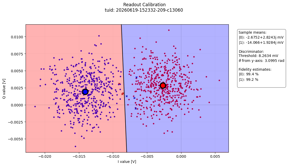
The image above shows that the measured IQ points are clustered in two groups as expected. We can now fit a line between the two groups and from there obtain the acq_threshold and the acq_rotation parameters, that we add to the qubit configuration:
import numpy as np

fit_results = analysis.fit_results["linear_discriminator"].params
acq_threshold = fit_results["acq_threshold"].value
acq_rotation = (np.rad2deg(fit_results["acq_rotation_rad"].value)) % 360

q0.measure.acq_threshold(acq_threshold)
q0.measure.acq_rotation(acq_rotation)
Verifying parameters#
We can quickly verify that the qubit parameters are set correctly by running again the readout_calibration_sched schedule with "ThresholdedAcquisition" as acquisition protocol. If the calibration was done correctly, we expect that when the state is prepared in the \(|0\rangle\) state or \(|1\rangle\) state, the thresholded acquisition will return 0 or 1 respectively. The results are then verified using a confusion matrix:
from sklearn.metrics import ConfusionMatrixDisplay
import matplotlib.pyplot as plt

single_qubit_device.cfg_sched_repetitions(1)

states = ManualParameter(name="States", unit="", label="")
states.batched = True

prepared_states = np.asarray([0, 1] * 500)
readout_calibration_kwargs = {
    "qubit": "q0",
    "prepared_states": states,
    "acq_protocol": "ThresholdedAcquisition",
}

gettable = ScheduleGettable(
    single_qubit_device,
    schedule_function=readout_calibration_sched,
    schedule_kwargs=readout_calibration_kwargs,
    real_imag=True,
    batched=True,
    max_batch_size=60,
)

measurement_control.settables(states)
measurement_control.setpoints(prepared_states)
measurement_control.gettables(gettable)
dataset = measurement_control.run("Readout Calibration Verification")

prepared_states = dataset.x0.values
measured_states = dataset.y0.values

ConfusionMatrixDisplay.from_predictions(
    prepared_states, measured_states, cmap="Blues", normalize=None
)
plt.title("Confusion Matrix")
plt.xlabel("Measured State")
plt.ylabel("Prepared State")

plt.show()
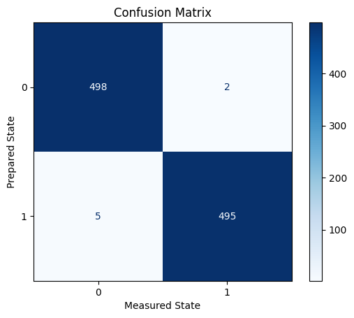
As expected, the threshold that we set did a good job of discriminating the qubit states (the discrimination is not perfect because the data points belonging to the two states slightly overlap).
Conditional Reset#
The conditional reset is implemented in Quantify as a gate. When we have a single Reset at the beginning of a schedule, we simply replace the Reset gate with the ConditionalReset gate, for example
schedule = Schedule()
#schedule.add(Reset("q0"))
schedule.add(ConditionalReset("q0"))
...
In other cases, however, we need to pass extra arguments to ConditionalReset that we illustrate below.
Example: Modifying the T1 schedule#
In this example, we use the schedule function t1_sched using the ConditionalReset instead of the standard Reset. We need to ensure that all acquisition protocols in the schedule are equal to "ThresholdedAcquisition".
from quantify_scheduler.qblox.operations import ConditionalReset
from quantify_scheduler.operations import X, Reset


# original T1 schedule
def t1_sched(
    times: np.ndarray,
    qubit: str,
    repetitions: int = 1,
) -> Schedule:

    schedule = Schedule("T1", repetitions)
    for i, tau in enumerate(times):
        schedule.add(Reset(qubit), label=f"Reset {i}")
        schedule.add(X(qubit), label=f"pi {i}")
        schedule.add(
            Measure(qubit),
            ref_pt="start",
            rel_time=tau,
            label=f"Measurement {i}",
        )
    return schedule


# updated T1 schedule
def t1_sched(
    times: np.ndarray,
    qubit: str,
    repetitions: int = 1,
) -> Schedule:

    schedule = Schedule("T1", repetitions)
    for i, tau in enumerate(times):
        schedule.add(
            ConditionalReset(qubit, acq_channel=0),
            label=f"Reset {i}",
        )
        schedule.add(X(qubit), label=f"pi {i}")
        schedule.add(
            Measure(
                qubit,
                acq_protocol="ThresholdedAcquisition",
                acq_channel=1,
            ),
            ref_pt="start",
            rel_time=tau,
            label=f"Measurement {i}",
        )
    return schedule
Running the T1 schedule using MeasurementControl#
The dataset returned by MeasurementControl will in this case have four rows of data, which are:
y0: contains the data establishing whether a qubit was reset or noty1: contains the actual (thresholded) measurementy2andy3: filled with NaNs (currentlyMeasurementControlexpectsScheduleGettableto return IQ values)
Below we run MeasurementControl again as before
single_qubit_device.cfg_sched_repetitions(1024)  # run and average 1024 times

# Configure the settable
time = ManualParameter("sample", label="Sample time", unit="s")
time.batched = True

times = np.array(list(np.linspace(start=1.6e-7, stop=4.976e-5, num=125)))

# Configure the gettable
gettable = ScheduleGettable(
    quantum_device=single_qubit_device,
    schedule_function=t1_sched,
    schedule_kwargs={"qubit": "q0", "times": times},
    batched=True,
    num_channels=2,
)

# Configure MeasurementControl
measurement_control.settables(time)
measurement_control.setpoints(times)
measurement_control.gettables(gettable)

dataset = measurement_control.run("t1")
Above we also passed num_channels=2 to the ScheduleGettable so that it knows to expect measurements on the same qubit, but separate acquisition channels.
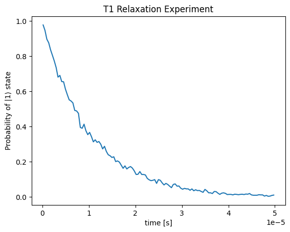
We now plot the contents of this dataset:
plt.plot(dataset.x0, np.abs(dataset.y1))
plt.xlabel("time [s]")
plt.ylabel('Probability of |1⟩ state')
plt.title('T1 Relaxation Experiment')
plt.show()
Note
Often, we can use an Analysis class on datasets to visualize the data and extract relevant parameters such as T1Analysis
Note on Execution Order#
Parallel ConditionalReset operations are not supported. For example, compiling the following schedule will raise a RuntimeError:
schedule = Schedule("")
schedule.add(ConditionalReset("q0"))
schedule.add(ConditionalReset("q1"), ref_pt="start")
and will have to be scheduled sequentially,
schedule = Schedule("")
schedule.add(ConditionalReset("q0"))
schedule.add(ConditionalReset("q1"))
Closing Remarks#
You can find more technical information and explanations of the different limitations in our reference guide.